System Sensor 2351e Smoke Detector Wiring Diagram

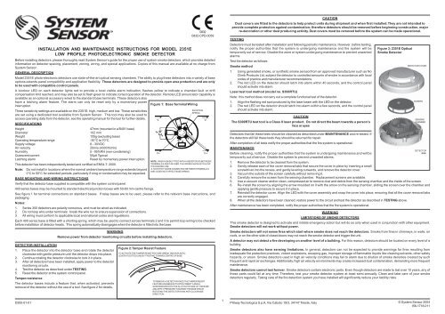
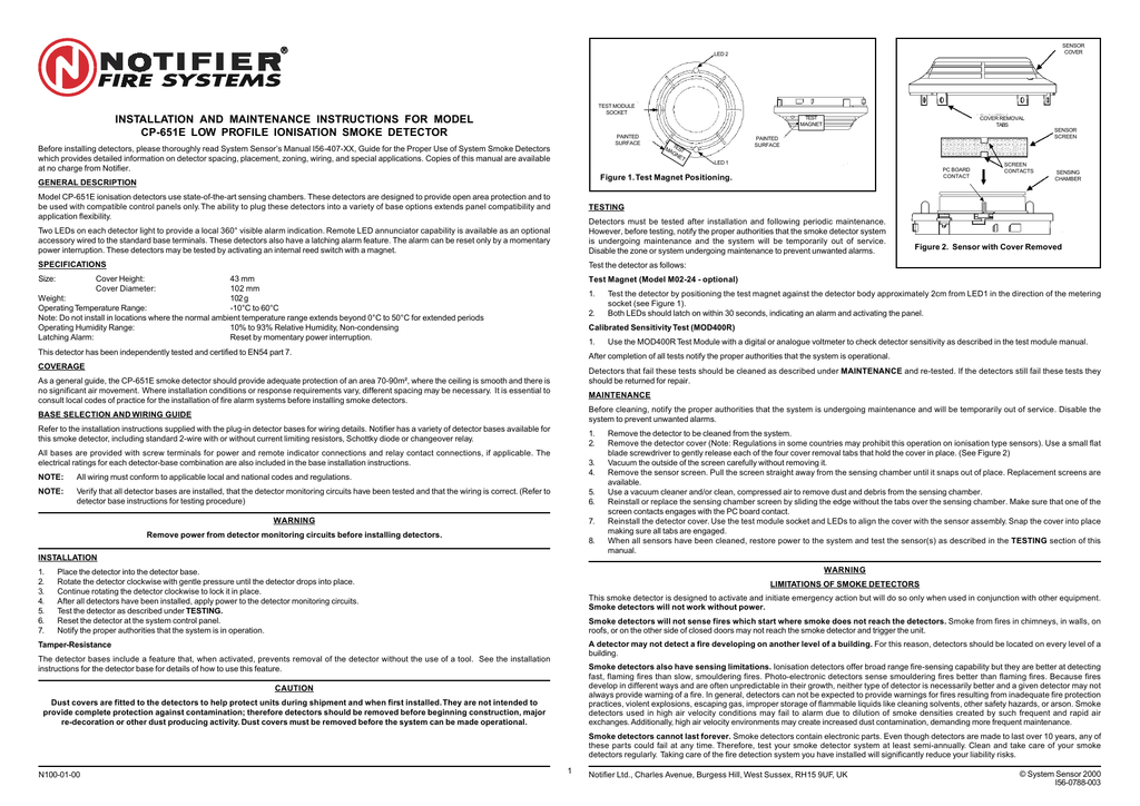
Installation And Maintenance Instructions For Model 2351e Low Profile Photoelectronic Smoke Detector Manualzz

2351e System Sensor Europe Manualzz

Installation And Maintenance Instructions For Model 2351e Low Manualzz
I56 1718 011 2351e A Manual Cpd Pmd System Sensor Canada
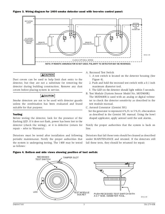
System Sensor 1400 Manual I56 0279
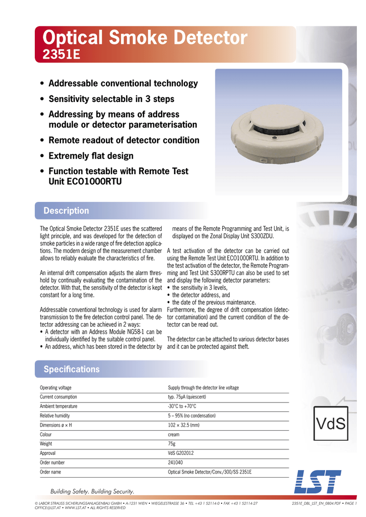
Lst 2351e User S Manual Manualzz
2351e system sensor europe manualzz installation and maintenance instructions for model low smoke detector स टम सर c o n v e t i a l b401 products wiring diagram melder magazines lst user s manual sv 7299 conventional spot type bases 2351e system sensor europe manualzz installation and maintenance instructions for model 2351e low installation and maintenance read more.
System sensor 2351e smoke detector wiring diagram.

C O N V E N T I O N A L Manualzz
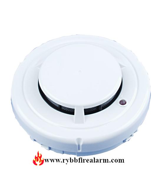
System Sensor 2351e Conventional Smoke Detector Rybb Fire Alarm
Descargar Manualzz
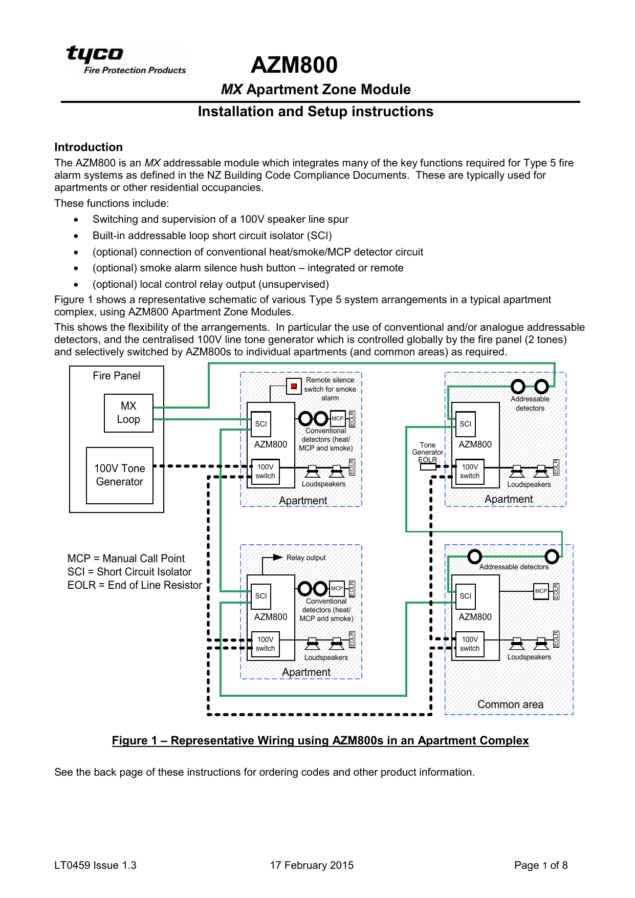
Lt0459 Azm800 Apartment Zone Module Installation And Setup Manualzz
Source : pinterest.com
